Each drive wheel has a 88 click resolution stripped paper pattern. This allows the robot to determine how far it's travelled and its current velocity.
The black and white strip transitions are detected by Hamamastu photo reflectors, data sheet here. For each transition from white to black, black to white a logic transition occurs.
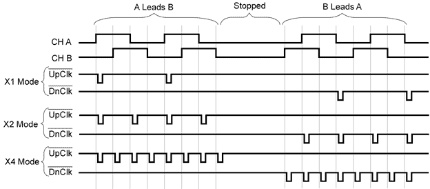
These sensors interface to the SH7032 MPU, whose IRQs cannot trigger on both the rising and falling edge of a pulse. As this would half the resolution the signals are initially passed though a USDigital LS7483IC, in X2 mode. On the rising or falling edge of each pulse this circuit will give a short 119Ás (8.2MOhm resistor used) pulse on its output. In this set up I only use channel A, channel B is just pulled low. Therefore the UpClk will output on the rising edge and DnClk on the falling edge. To get an up down pulse on one output the UpClk and DnClk channels are combined via a 74LS00 NAND gate then its output is sent to the MPU.
LS7183 Timing Diagram:

This means the MPU will now read a count for each black/white white/black transition of the wheel clicks.