The robot is able to sense when it was hit an object by the bump skirt around the edges of the chassis. When the bump skirt is pressed one or more of the 24 micro switches will change state from normally open (no) to closed.
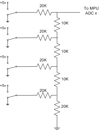
The switches are wired into one of 4 R2R resistor ladder networks, one for the front left, front right, rear left and rear right. I found the the difference between values from the R2R for more than 4 bits caused values to become indistinguishable to the MPU, resulting in false or inaccurate readings.
The analogue value from the ladder networks is sampled but the SH7032 MPU where it determines where on the robot a collision has occurred.
The figure below details the circuit diagram for one of the 4-bit R2R ladder networks.
