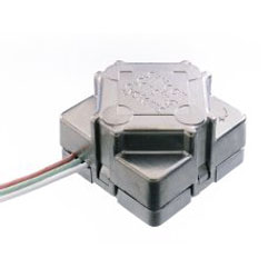
The gyro sensor is a silicon sensing systems CRS03 - http://www.siliconsensing.com/products/products_crso3.htm. This gyro has is quite expensive, but it has excellent drift characteristics and is able to measure a good rate of turn (200 deg/sec)

The sensor allows the robot to determine it's orientation and how far it's really turned. The most important use for the gyro is when the robot is linked up to the host system and is creating environment maps, it allows the system to determine the direction the robot is heading.
The gyro's output is sampled at 500Hz, of which the average is calculated every 50Hz. Therefore giving an average sampling rate of 10Hz.
The gyro has an idle output voltage of ~2.5v, this idle voltage (NullOffset) has to be calibrated each time the robot is started; as it can vary slightly. The calibration loop takes the average output voltage (When the robot it not moving) over 3 seconds. Once this is calculated it is then used to determine the rate of turn of the gyro during operation.
The GyroRate and GyroAngle are calculated thus:
AverageADCVoltage = AverageADCVoltage Over 50 samples
AverageADCVoltage = AverageADCVoltage - NullOffset;GyroRate = AverageADCVoltage;
GyroRate = GyroRate / 10; // There are 10mV per deg/sec turned
GyroRate = GyroRate / 10; // Divide by the sample frequency; 10Hz.
GyroAngle = GyroAngle + GyroRate;
The main problem with calculating the GyroAngle this way is that it will drift over time, to help combat this the robot can be set to re-calibrate the null offset every few minutes. In tests the gyro will only drift a few degrees every 10min or so, which is good enough for the robot's mapping requirements.
It would be possible to use a digital compass to keep the gyro calibrated. The idea being that the gyro would provide very accurate orientation readings over a short period of time, where as the digital compass would be accurate over a long period of time. The Devantech digital compass is one such device - found here.