![]()
![]()
![]()
![]()
![]()
![]()
![]()
![]()
The robot is fitted with 8 Polaroid sonar transducers, which are multiplexed to a 6500 range finding module.
![]()
Figure 1.
As the range finder requires a lot of hardware interface (relatively) there is simply not enough resource on the SH7032 MPU to have 8 individual range finding units, not to mention the cost!!!! To solve this problem the sensors are multiplexed into one range finding unit. To do this I used 8 PVU414 opto-isolated relays, which switch the drive from the range finding unit to the sensors. The PVU414's are controlled via a 74HC138 multiplexer IC, allows the MPU to select with sonar is fired and therefore which one will receive the echo.
Figure 2 shows the multiplexing circuit diagram
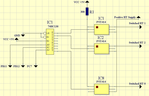
Figure 2.
In my initial design I used opto-isolated triacs, however these caused all sorts of problems when receiving an echo given the amount of current they need to switch on.
The basic operation of calculating the distance from the robot to the an object using the sonar is to fire the sonar, start a timer counting and set up and IRQ to stop the counter when the echo returns. Given the resolution of the timer and knowing the speed of sound in air the robot can calculate how far away an object is.
The robot uses a 75us timer to measure the delay between firing the sonar and the echo being received. This equates to a resolution of 2.5cm/sec @ 333m/s (speed of sound in air).
To measure the distance between a sonar transducer and the closest object the following algorithm is used:
Initialise Timer (75uS IRQs)
Start Timer
Wait 900uS to clear BINH (Blank inhibit - prevents the
sonar's ringing being mistaken as an echo. 900uS is less that the
factory setting of 2380uS, this allows for closer objects to be detected.
The clear BINH option and length of the wait are configurable)
Loop Until Ping Received (Time out after 1.875mS)
Divide the time by 2 (Time is the total flight time)
Calculate the distance travelled.
Electrical Issues.
Due to the high voltage and current demands of the sonar's, it was found that having the earthing of the shells of the sonar transducers connected to the robot chassis earth caused reading errors. Therefore I had to find a way of connecting the bump skit, holding the sonar's, to the main chassis of the robot, but ensuring they were electrically isolated, therefore preventing any earthing loops being created. This was achieved by using a piece of PCB, with the copper tracks removed. It is fixed onto the robot chassis and the bump skirt it fixed onto the PCB. This photo below show this set up:
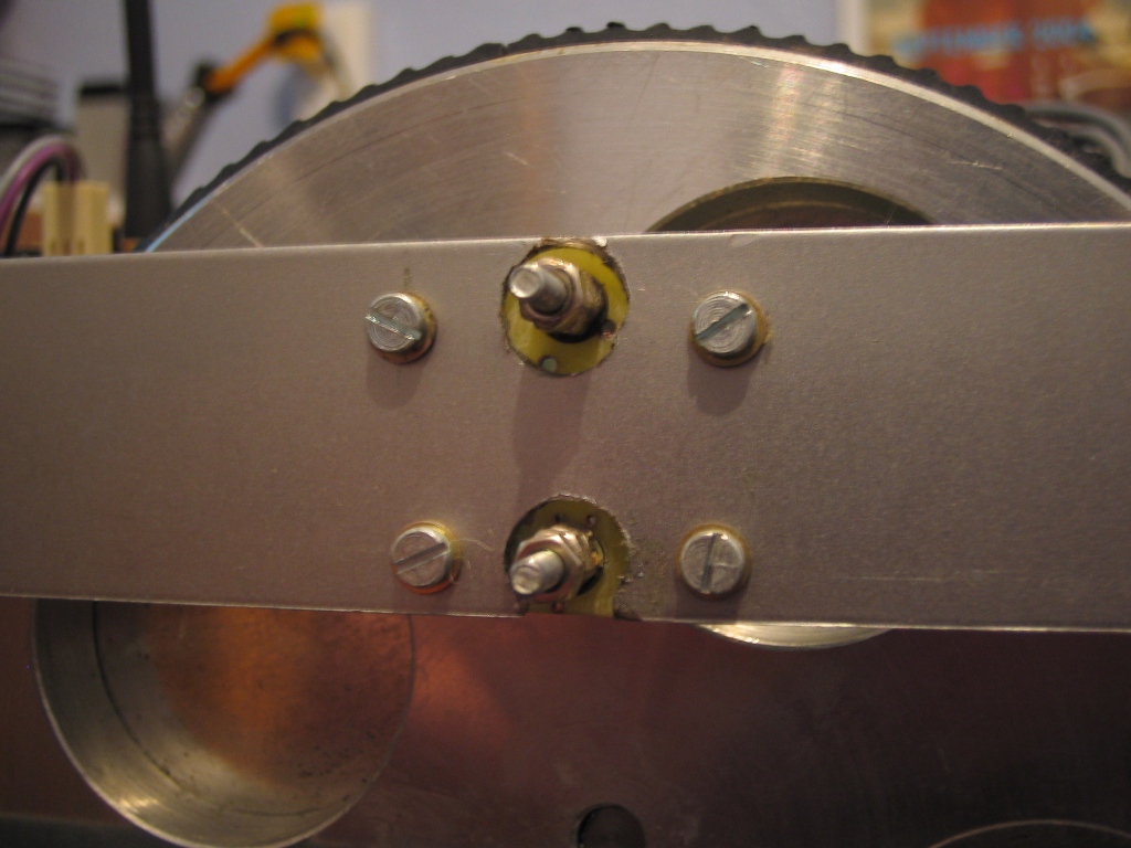
Figure 3